
Here I describe the procedure followed to remove the traction battery of a Peugeot iOn (Mitsubishi i-MiEV) to replace a cell.
I replaced a LEV50 cell with a LEV50N cell because I couldn’t find a used LEV50 replacement. The characteristics of the two models are similar, however.
Caution
Carrying out the operations illustrated in this article involves both crushing risks as you have to work under the car, and electrical risks as you have to work on a high-voltage battery!
Car preparation
- Before disconnecting the battery, read the battery diagnostic data if desired.
To identify the cell to be replaced, the OBDLink LX tool can be used with the Android applications OBDZero or CaniOn:


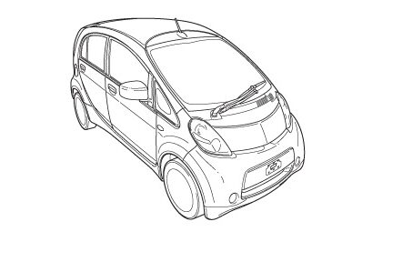
Car lifting
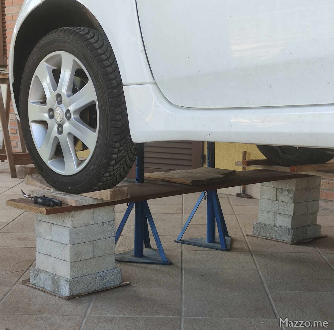
- Raise the car approximately 35 cm using the appropriate lifting points (this height allowed me to lower and remove the battery using a pallet jack, leaving the car resting with its wheels on some bricks).
- There are two jacking points for lifting the car, one at the front center and one at the rear center. This allows you to lift the car without twisting the battery.
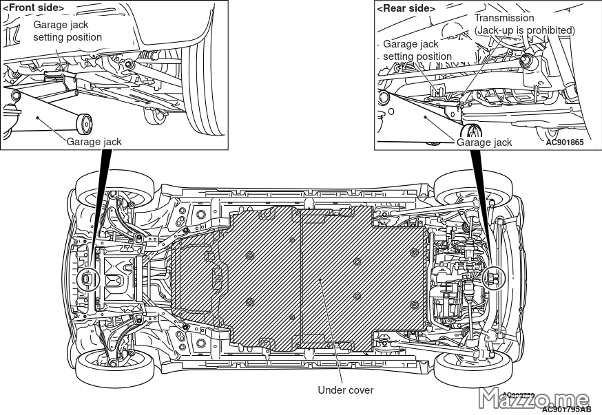
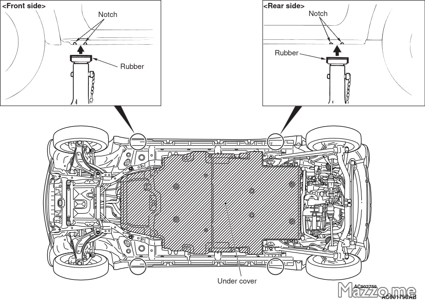
Jack support points. - If you want to rest the car on the frame and not on the wheels, there are four support points, but the rigid racks would prevent the battery from being removed from the side of the car:
Rigid racks support points. - If you have a lift, there are four support points for lifting the car, and the battery can be removed more easily by lifting the car after placing the battery on a support and unscrewing the battery:
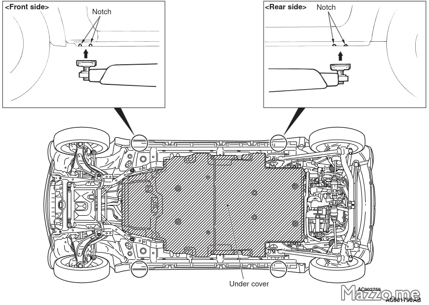
Lift support points.
- There are two jacking points for lifting the car, one at the front center and one at the rear center. This allows you to lift the car without twisting the battery.
I placed a board between the two front wheel supports to keep them together because when lowering the car and compressing the suspension the wheels tend to push outwards:
Battery removal
- Disconnect the 12 V service battery.
Battery disconnector
Caution
Remove the battery disconnector before performing any operation on the battery!
- Unscrew the service lid to access the battery disconnector located under the driver’s seat (this can be done by moving the driver’s seat all the way back without having to remove the seat):
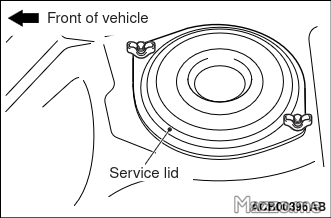
Battery disconnector service lid. - Remove the battery disconnector:
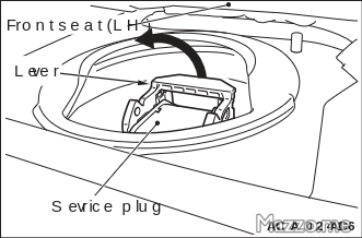
Battery disconnector. 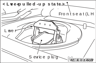
Battery disconnector. 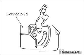
Battery disconnector.
Battery cover
- Remove the two covers under the battery secured with screws and plastic rivets, first the front one and then the rear one:
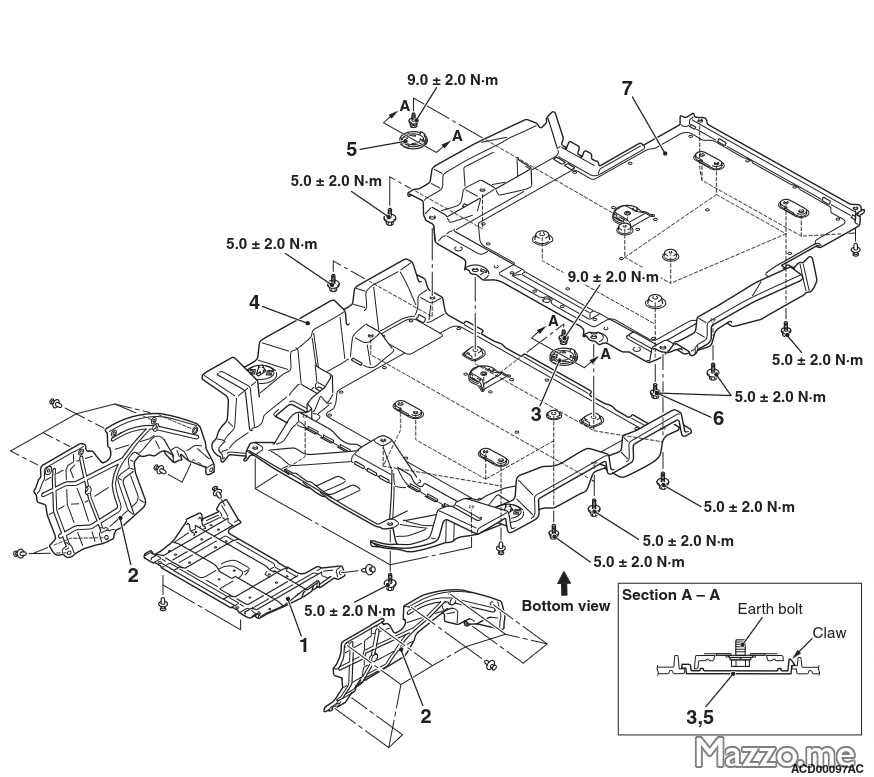
Lower battery cover screws and rivets.
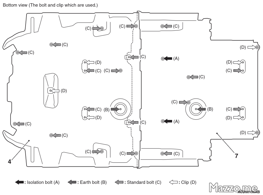
| Screw | Tightening torque |
|---|---|
| Lower battery cover | 5 ± 2 Nm |
| Lower battery cover ground | 9 ± 2 Nm |
Battery cables
Caution
Check the voltage on the cables you are going to work on before touching them!
- On the lower right side of the battery, open the battery cable connection service lid:
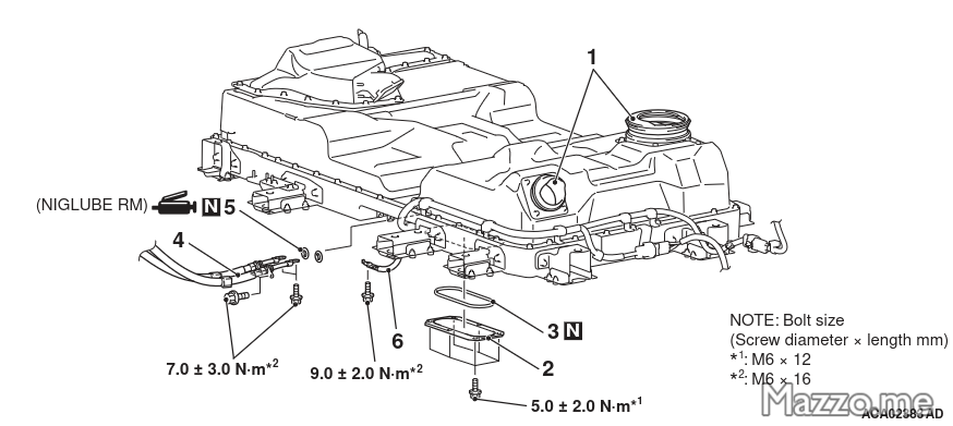
Power cable connections.
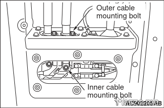
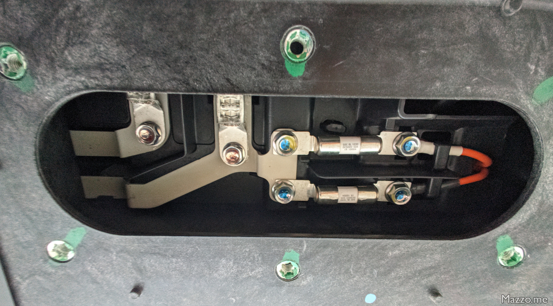
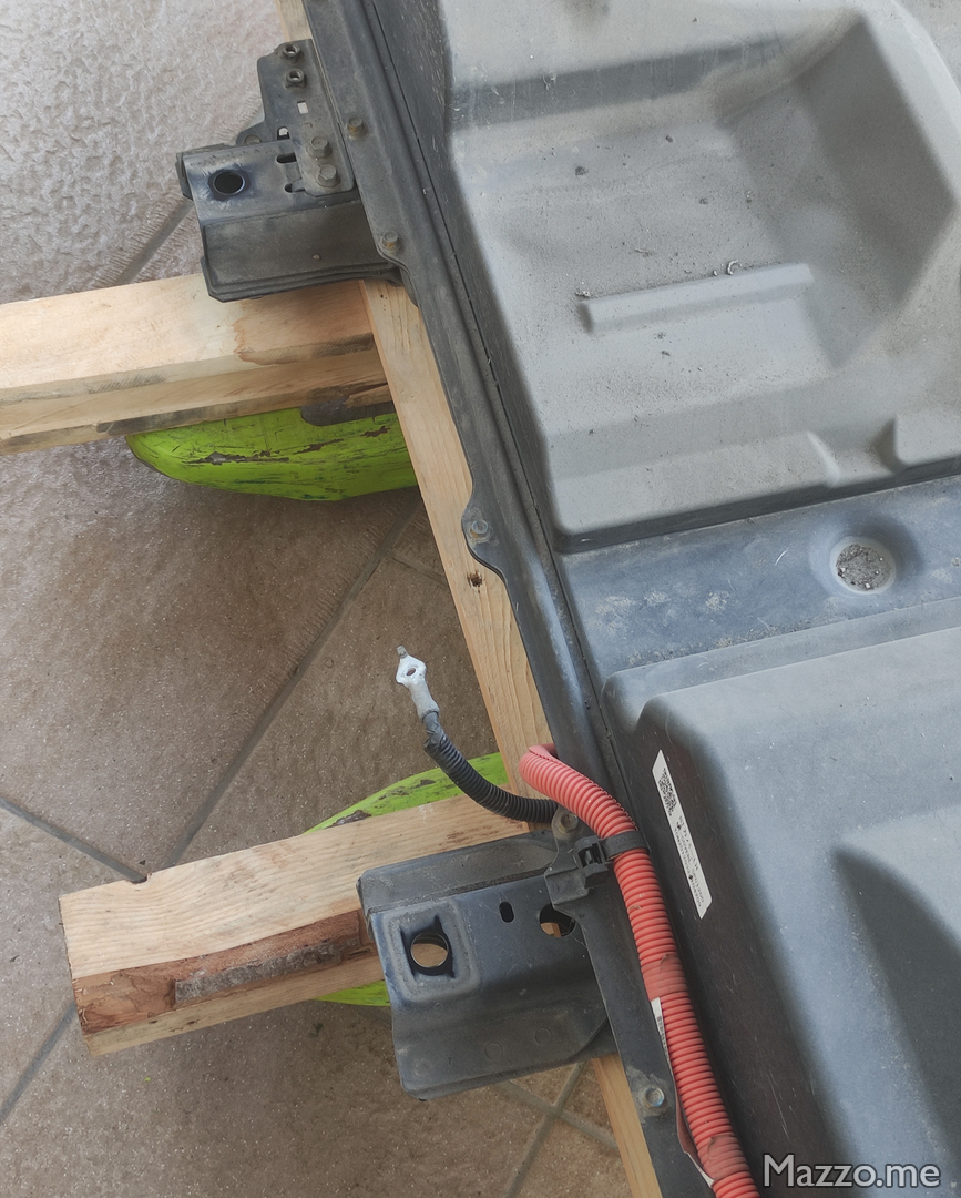
- Disconnect the two orange cables via the two internal screws and the two external screws and the ground cable from the car chassis:
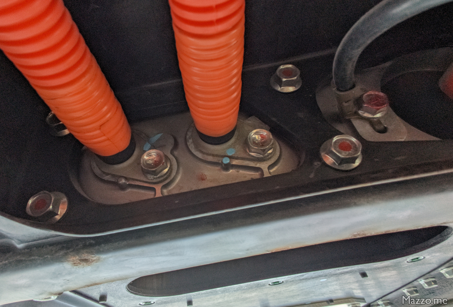
Power cables.
| Screw | Tightening torque |
|---|---|
| Battery cable connection service lid | 5 ± 2 Nm |
| Internal battery cable fixing | 7 ± 3 Nm |
| External battery cable fixing | 7 ± 3 Nm |
| Battery ground | 9 ± 2 Nm |
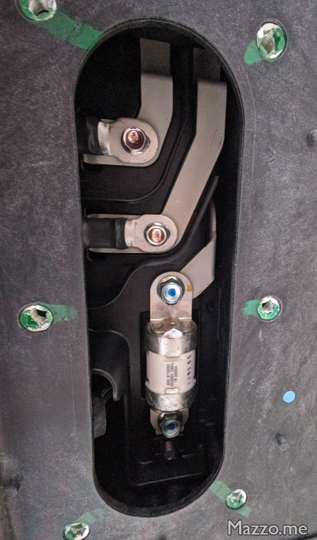
- On the lower left side of the battery, open the fast charging cable connection service lid:
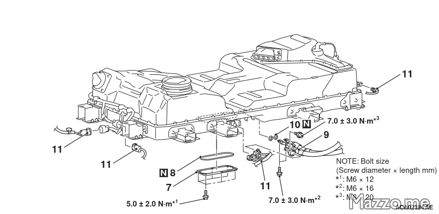
DC charging cable connections.
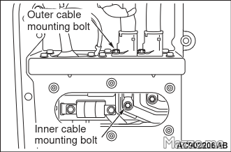
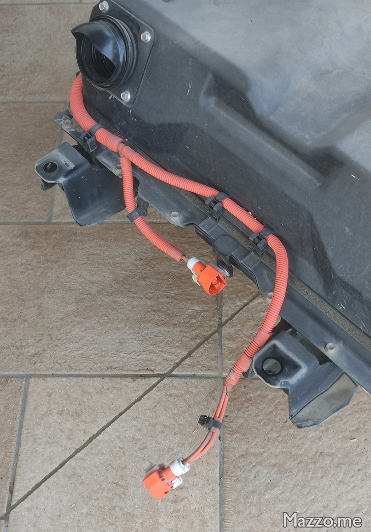
- Disconnect the two orange cables via the two internal screws and the two external screws and the four multi-pin connectors of the battery signals:
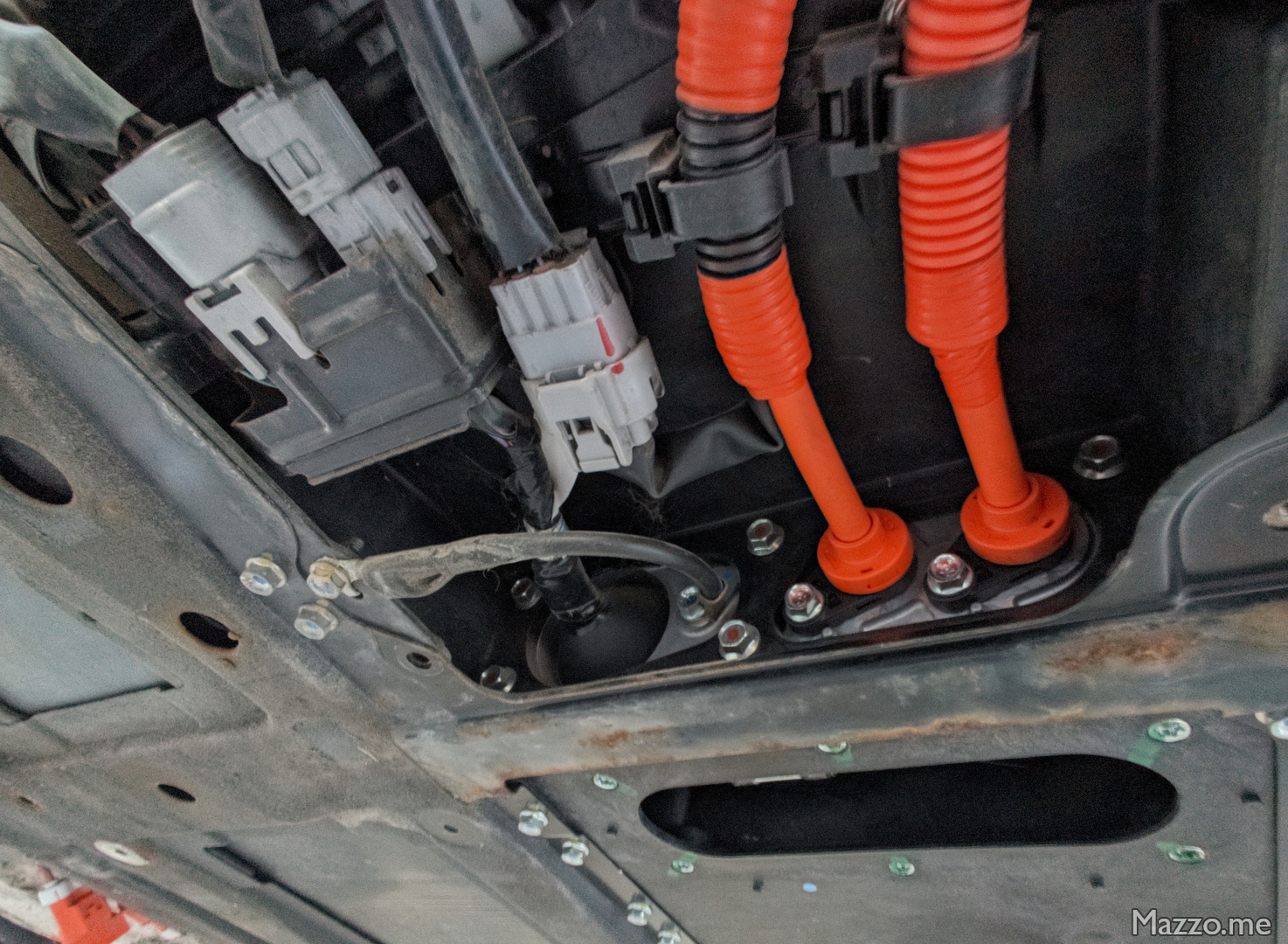
DC charging cables and battery signal connectors.
| Screw | Tightening torque |
|---|---|
| Fast charging cable connection service lid | 5 ± 2 Nm |
| Internal fast charging cables fixing | 7 ± 3 Nm |
| External fast charging cables fixing | 7 ± 3 Nm |
- On the back left of the battery disconnect the battery cooling fan connector:
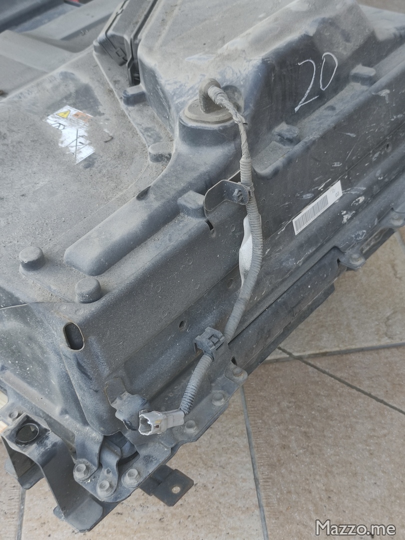
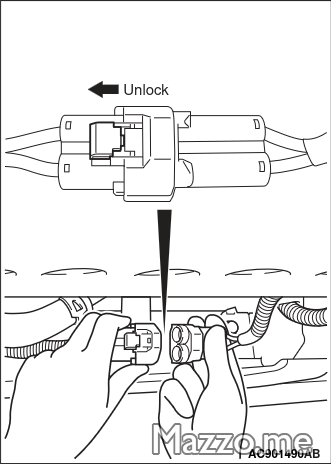
Battery cooling fan connector. - At the front of the battery disconnect the two connectors of the heating boiler and the air conditioning compressor:
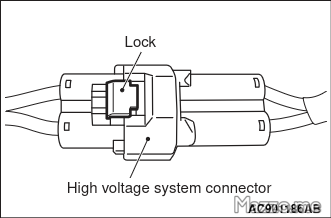
Heating boiler and air conditioning compressor connector.
Battery supports
- On the rear right and left, remove the two plates that connect the battery to the car’s chassis:
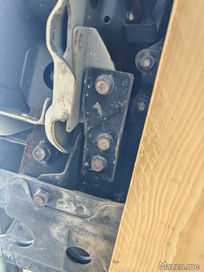
Battery fixing plate. - Loosen the ten battery support screws without unscrewing them:
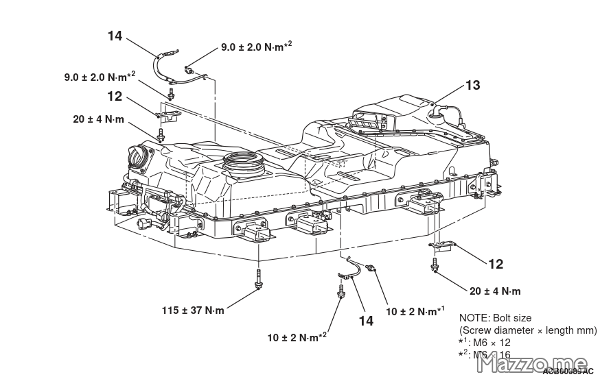
Battery fixing screws.
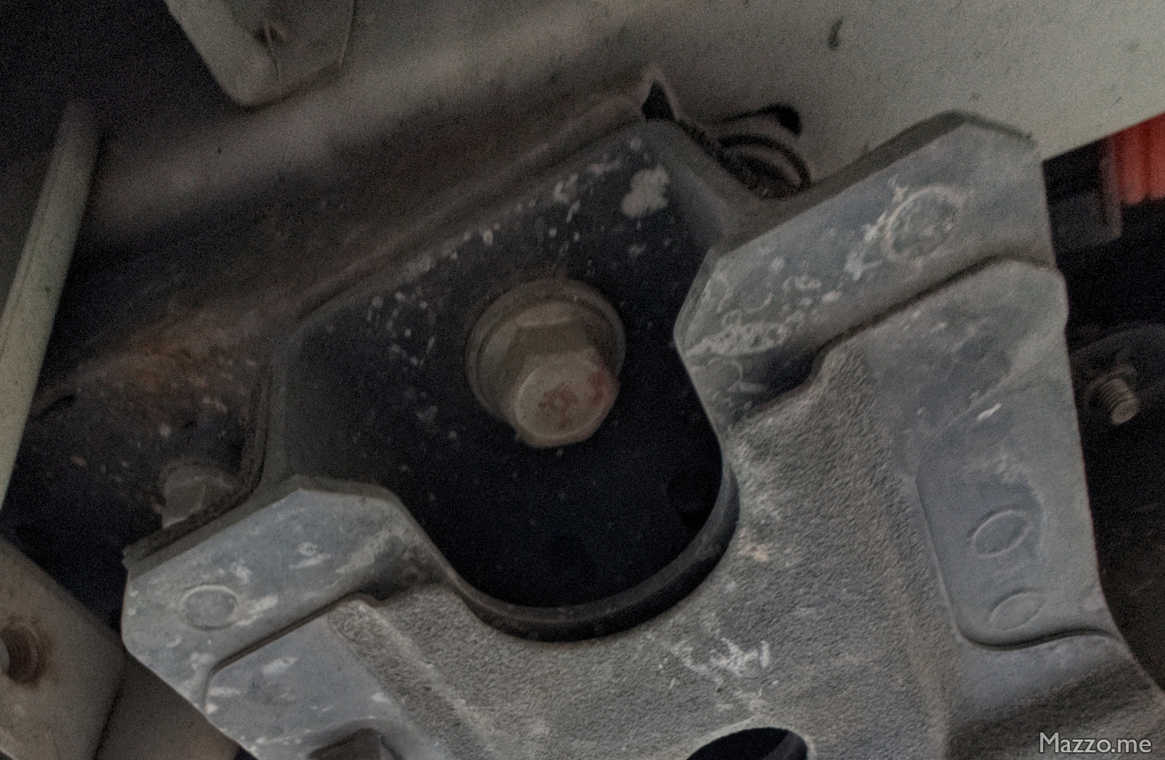
- Support the battery from the bottom to be able to unscrew and lower it (in my case I used a pallet jack with wooden beams as shims and some planks under the battery to be able to lower it a little at a time).
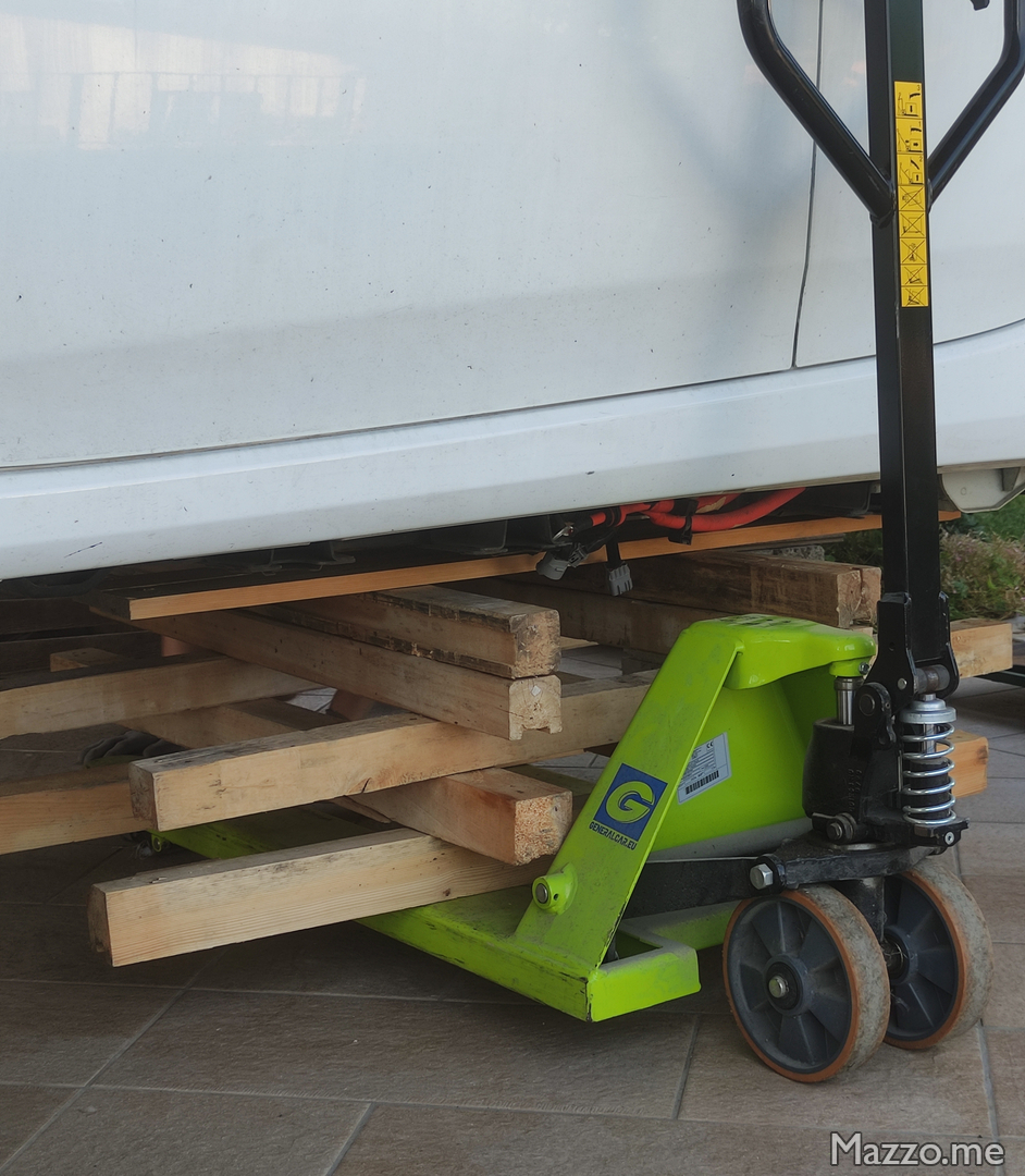
Battery support with pallet jack.
| Screw | Tightening torque |
|---|---|
| Battery support | 115 ± 37 Nm |
| Battery frame connection plate | 20 ± 4 Nm |
- Completely unscrew the battery support screws and lower it, paying attention to the two gaskets on the front that connect the inside of the battery to the passenger compartment of the car and making sure that all the cables have been disconnected:
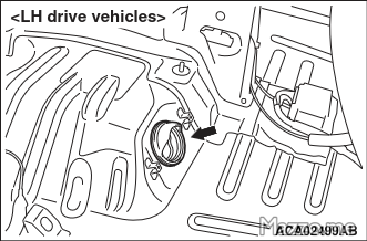
Battery cooling duct gasket.
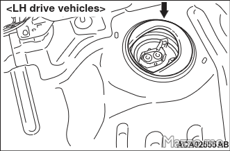
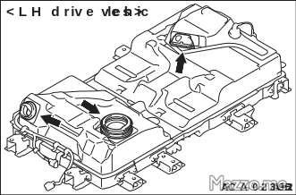
- Remove the battery from the car:
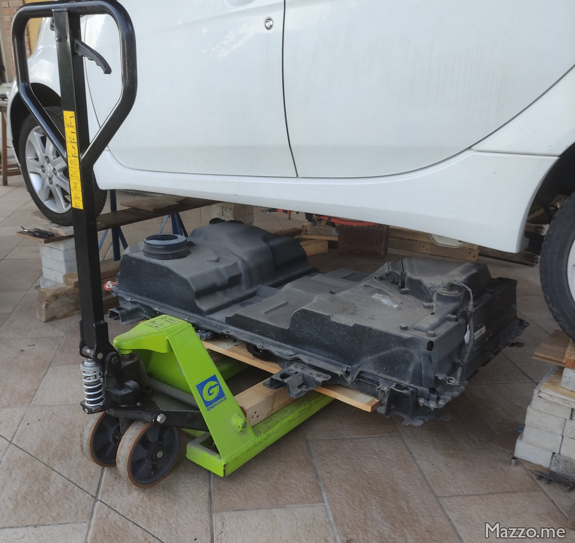
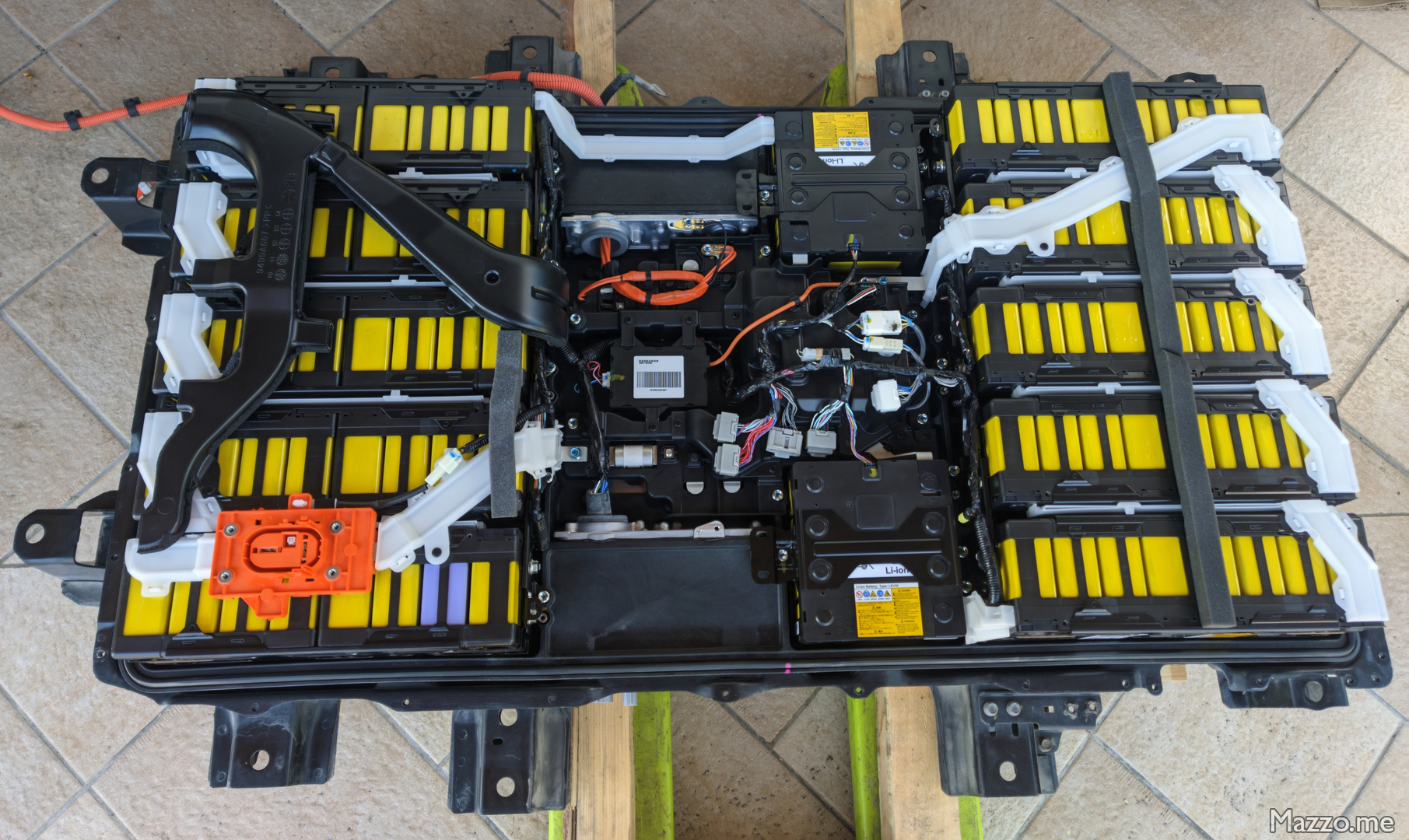
Battery removed.
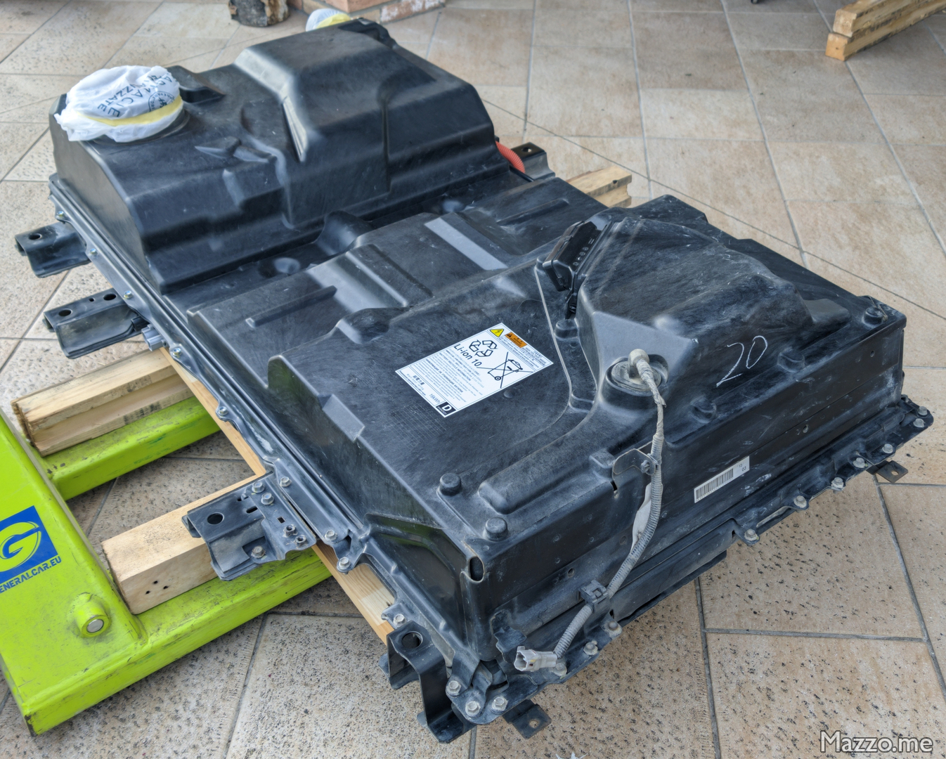
Upper battery cover
- Unhook the sheaths attached to the upper battery cover.
- Remove the four black caps around the battery disconnect connector and unscrew the four screws that secure it to the upper casing:
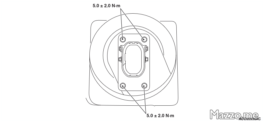
Battery disconnector support.
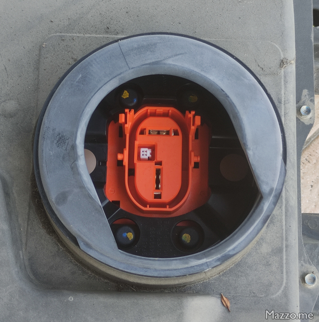
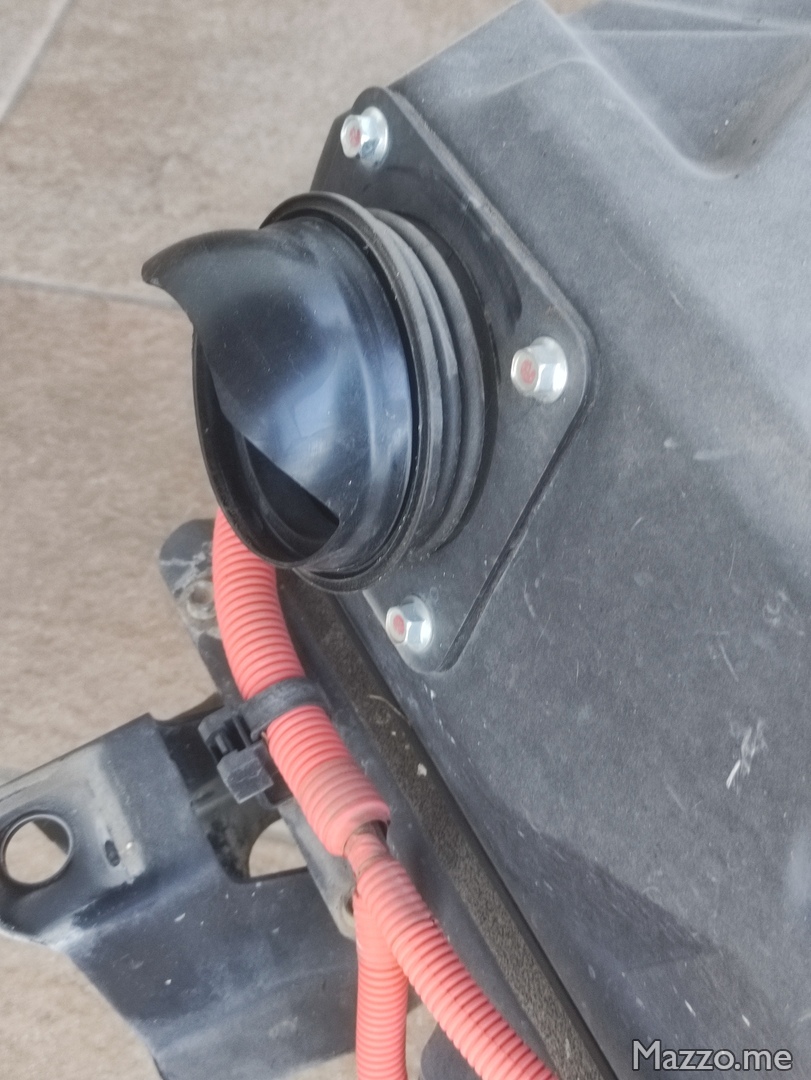
- Remove the four screws securing the battery cooling duct gasket:
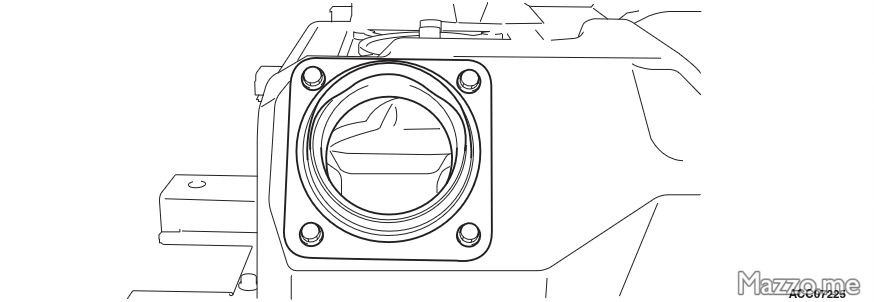
Battery cooling duct gasket support.
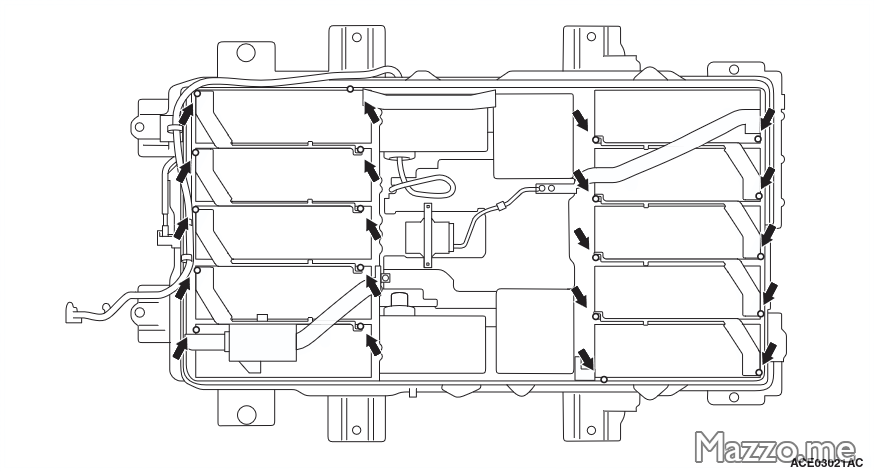
- Remove the thirty-eight screws that secure the upper battery cover and open it (in the MY 2011 version there are 48 screws, in the MY 2012 and later versions there are 38 screws and they have different tightening torques):
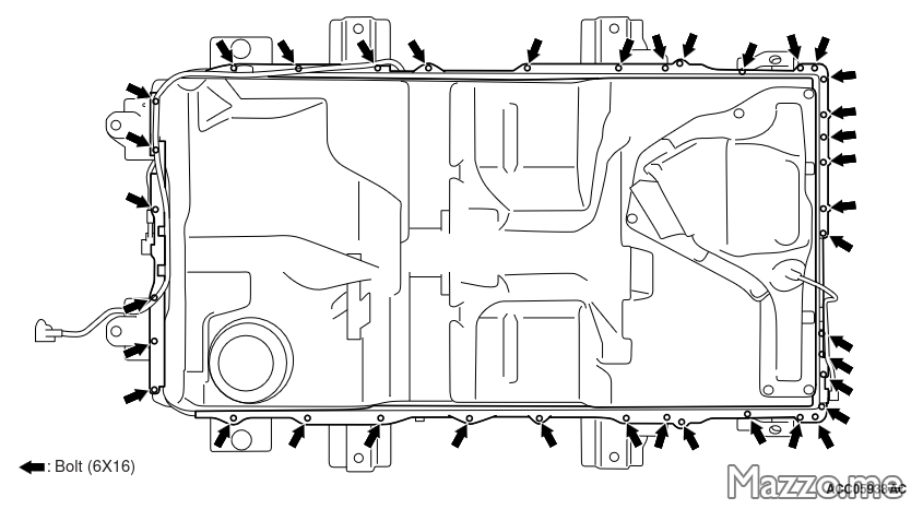
Upper battery cover fixing screws. - When reassembling, the screws must be tightened following the following order:
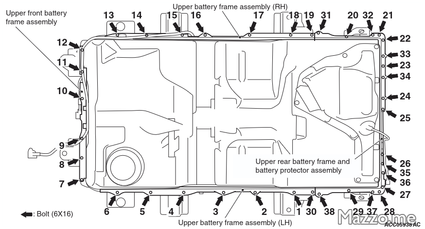
Upper battery cover fixing screws.
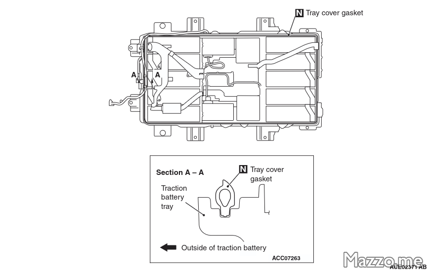
- Remove the top cover from the battery:
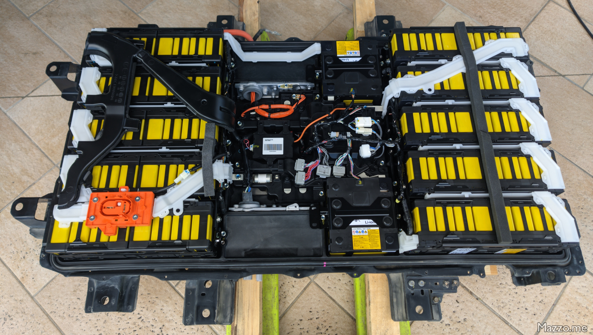
Battery cover removed.
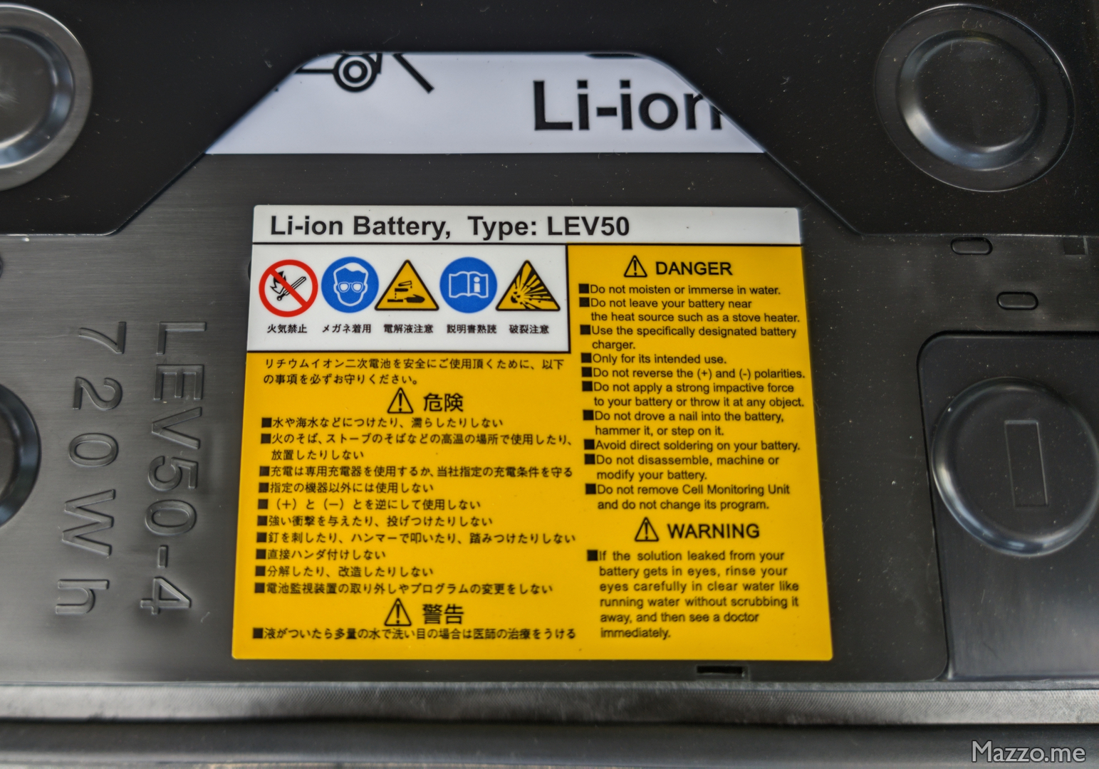
| Screw | Tightening torque |
|---|---|
| Battery disconnect connector support | 5 ± 2 Nm |
| Upper battery cover MY 2011 (48 screws) | 7,3 ± 1,2 Nm |
| Upper battery cover MY 2012 (38 screws) | 10 ± 2 Nm |
Module disassembly
- Locate the module containing the cell to be replaced.
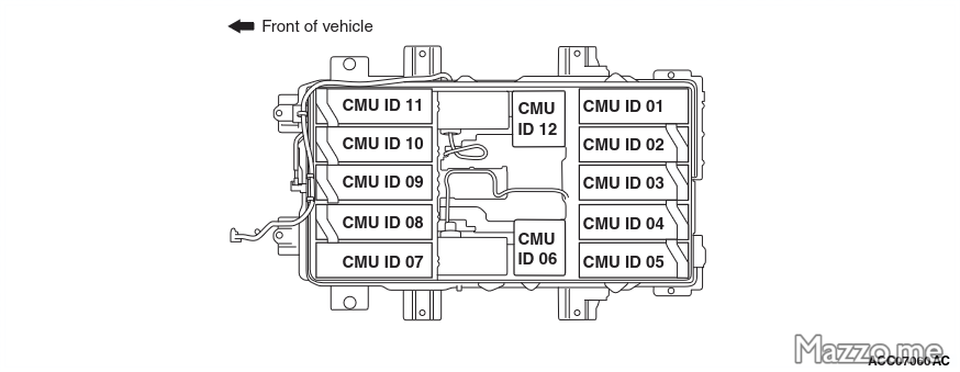
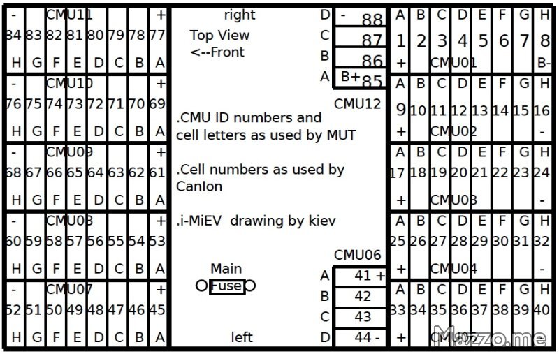
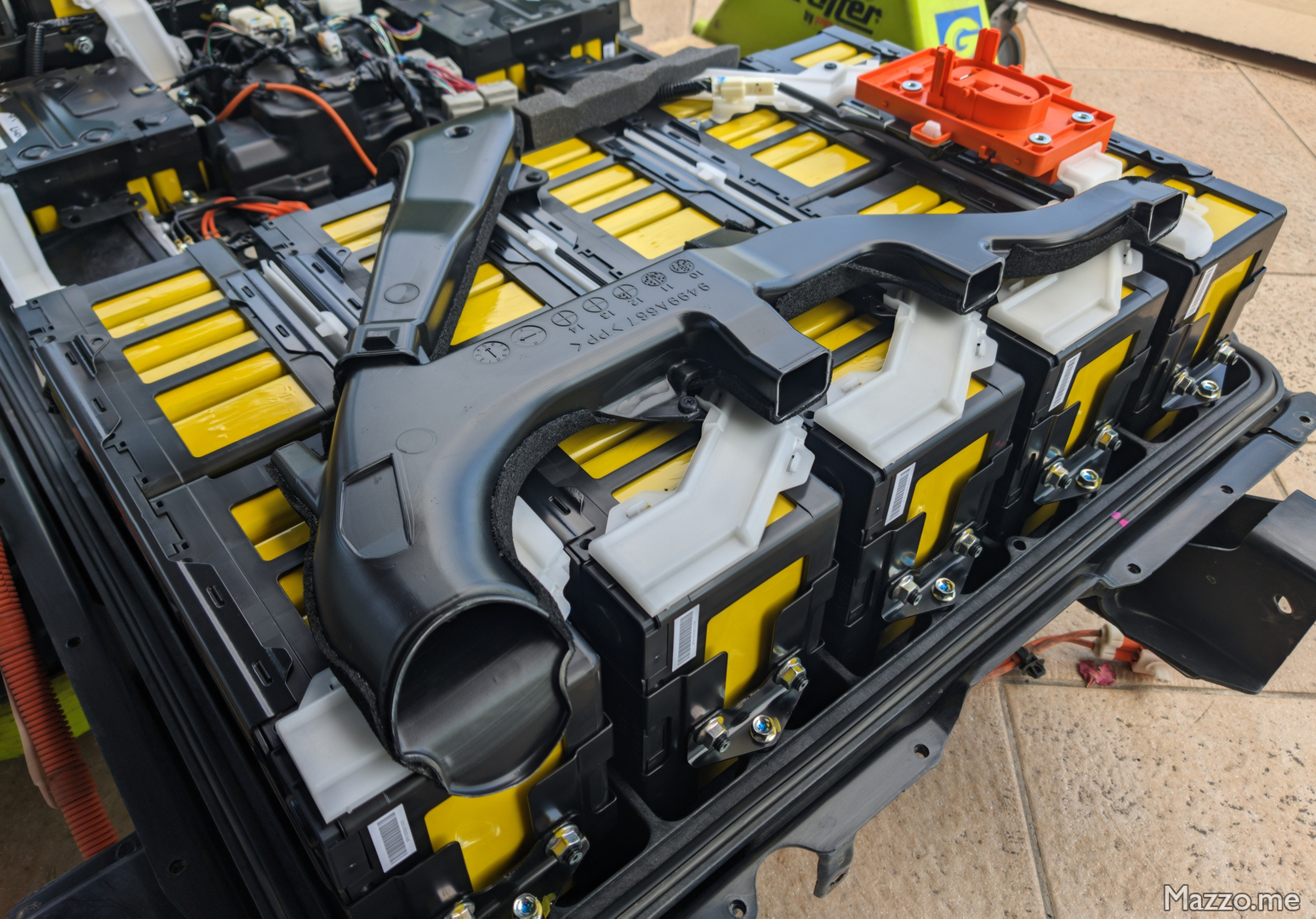
Battery cooling duct
- If necessary, remove the battery cooling duct secured with three plastic rivets:
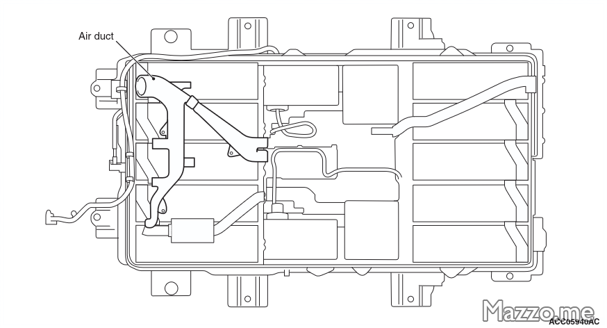
Battery cooling duct.
Bus bar
- Remove the bus bars needed to extract the module (in my case the bus bar with the connector to disconnect the battery):
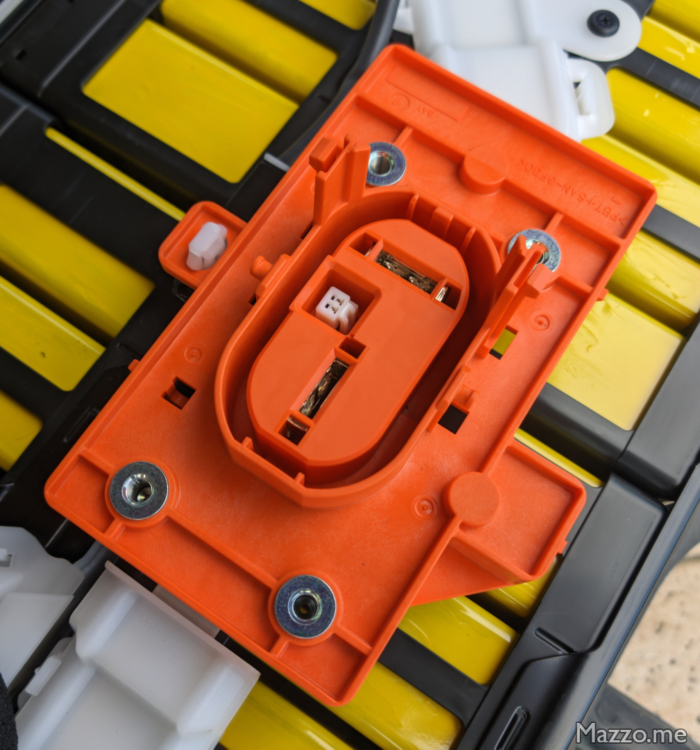
Battery disconnector connection. - If necessary, remove the padding above the module to be removed:
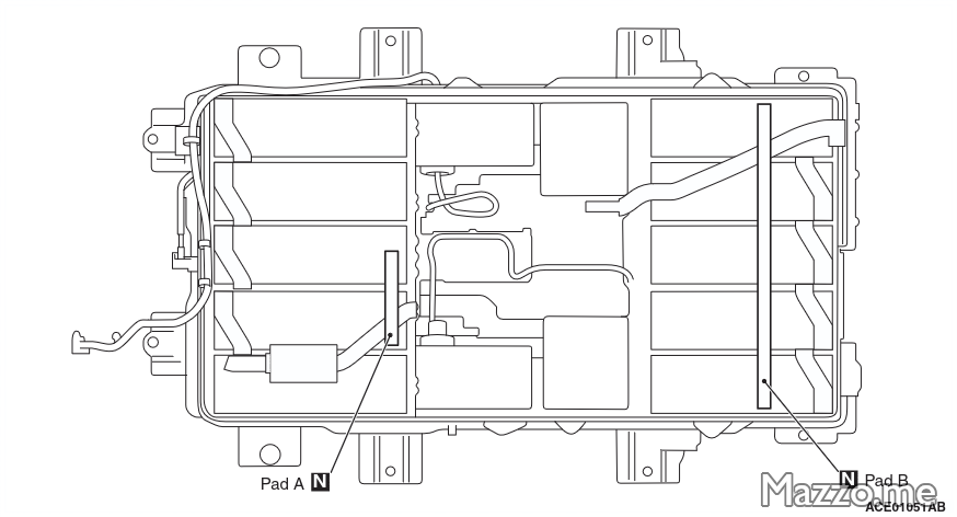
Upper battery cover padding.
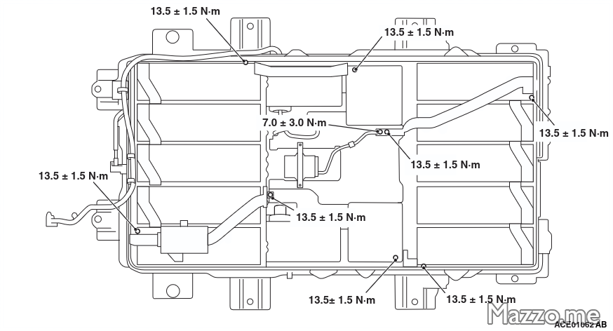
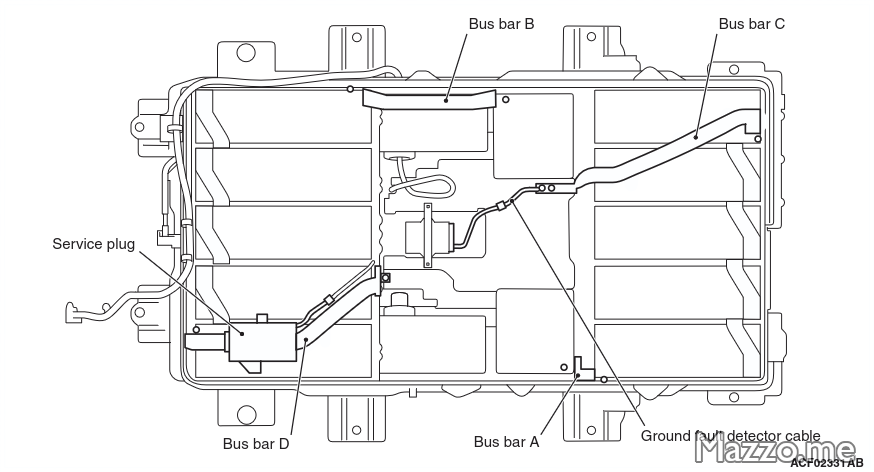
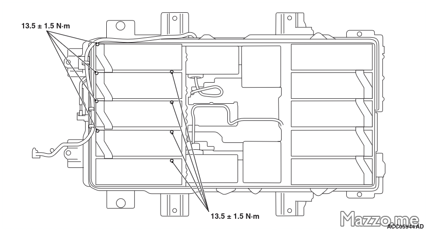
| Screw | Tightening torque |
|---|---|
| Bus bar on cell terminals | 13,5 ± 1,5 Nm |
Module
- Disconnect the electronic board connector of the module to be removed.
- Unscrew the supports of the module to be removed from the battery box:
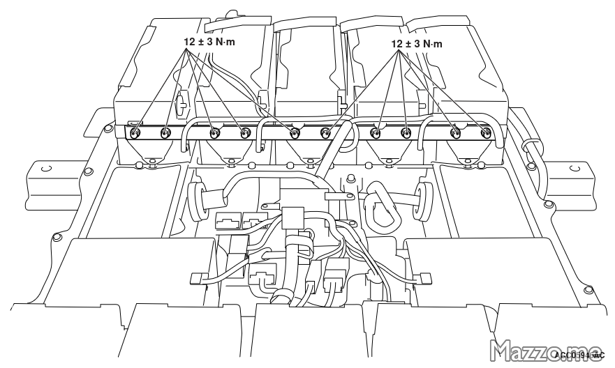
Module supports.
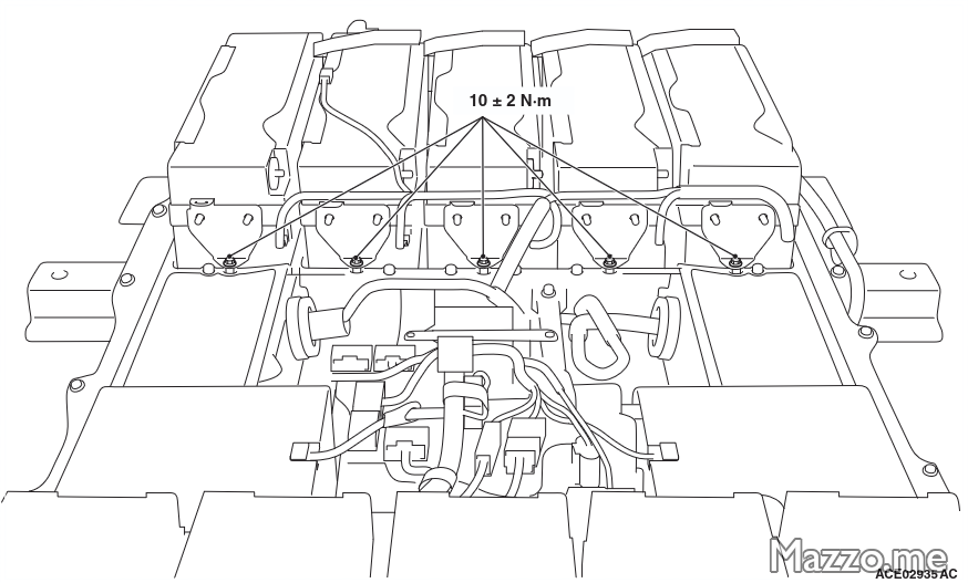
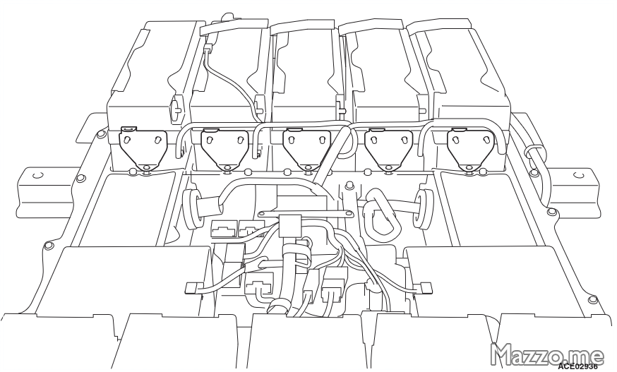
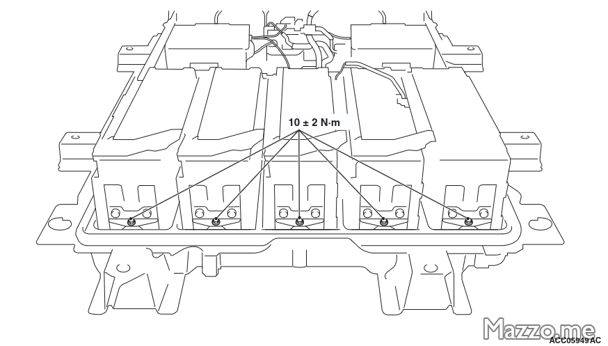
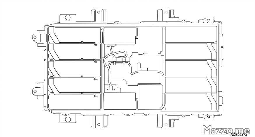
- Remove the module from the battery:
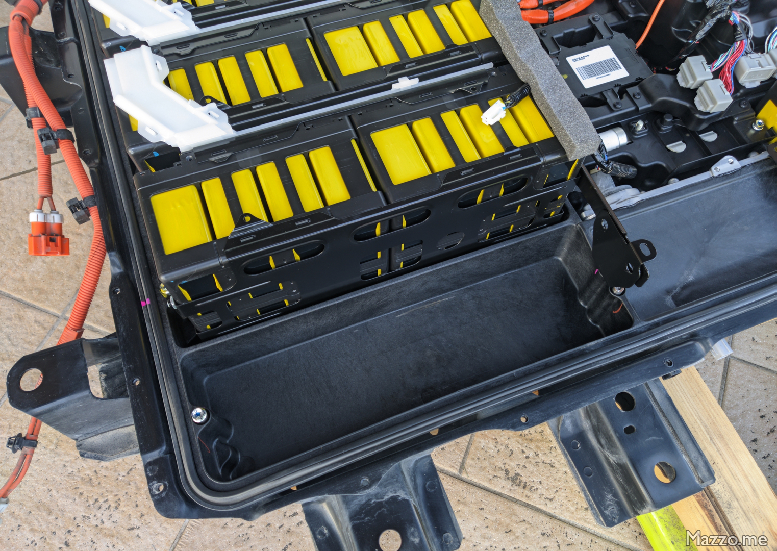
Module removed.
| Screw | Tightening torque |
|---|---|
| Module support bracket on module | 12 ± 3 Nm |
| Module support bracket on battery box | 10 ± 2 Nm |
Cell replacement
- In the removed module, locate the cell to be replaced.
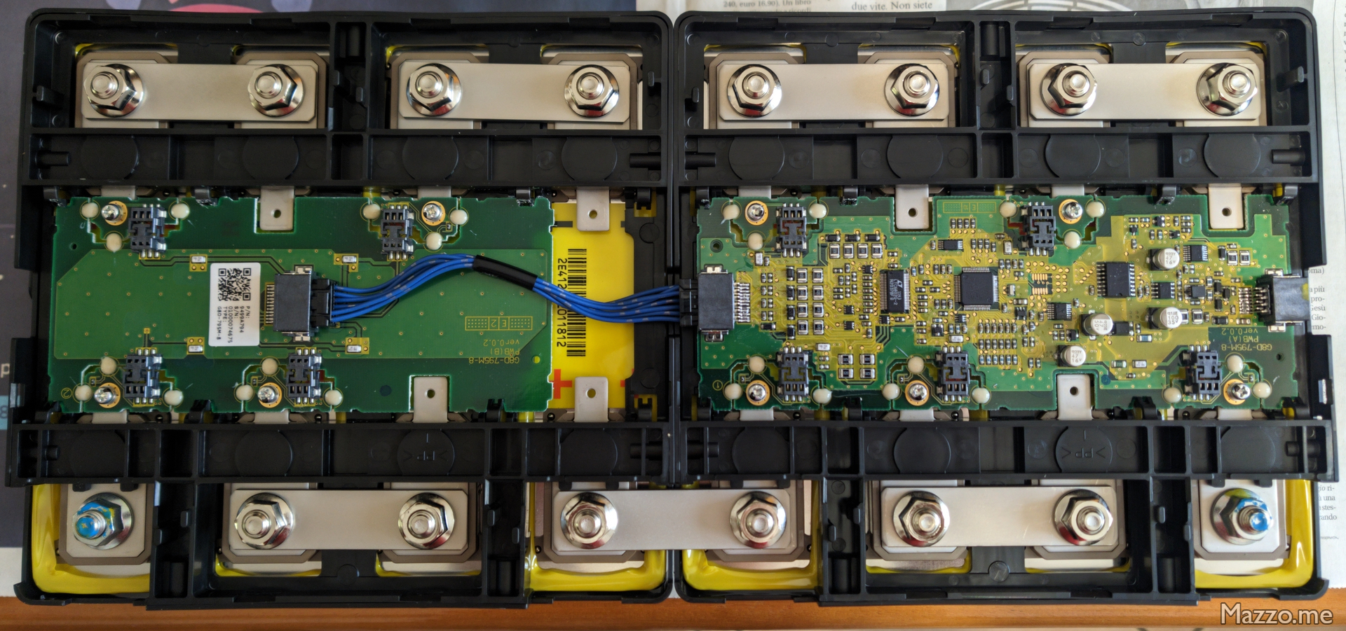
Module electronic boards. - First remove the electronic board above the cell to be replaced, then the three bus bars on the side of the cell to be replaced, then the black plastic part that holds the cells:
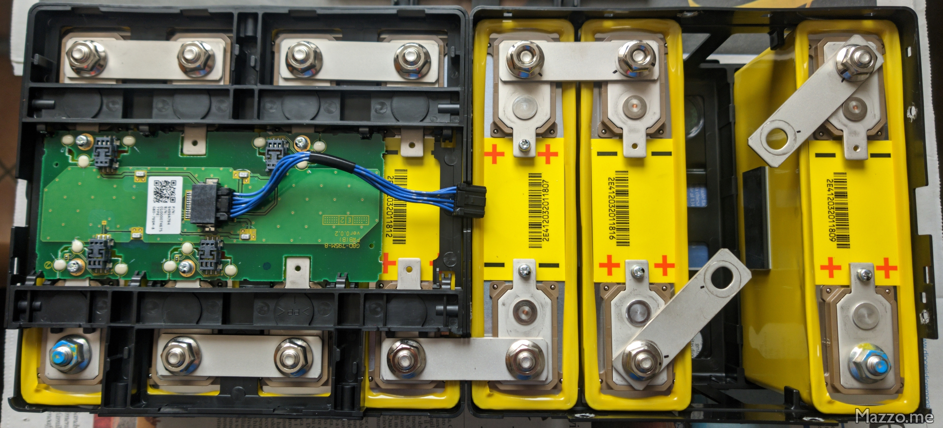
Cell removed from module.
In my case, having a LEV50N cell (purple) as a spare and not a LEV50 cell like the originals (yellow), the dimensions of the cells are slightly different, so I had to make some adapters to be able to fit it correctly.
The heights of the cells are different:

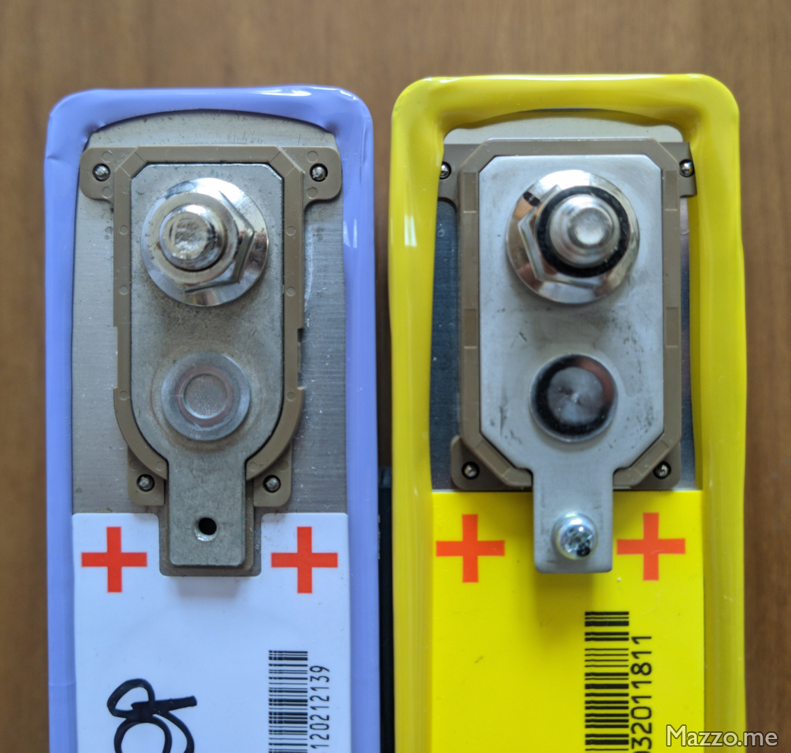
There are also differences in the shape and thickness of the cell terminals:
Under the cell I inserted a 3D printed PETG spacer with 100% infill:
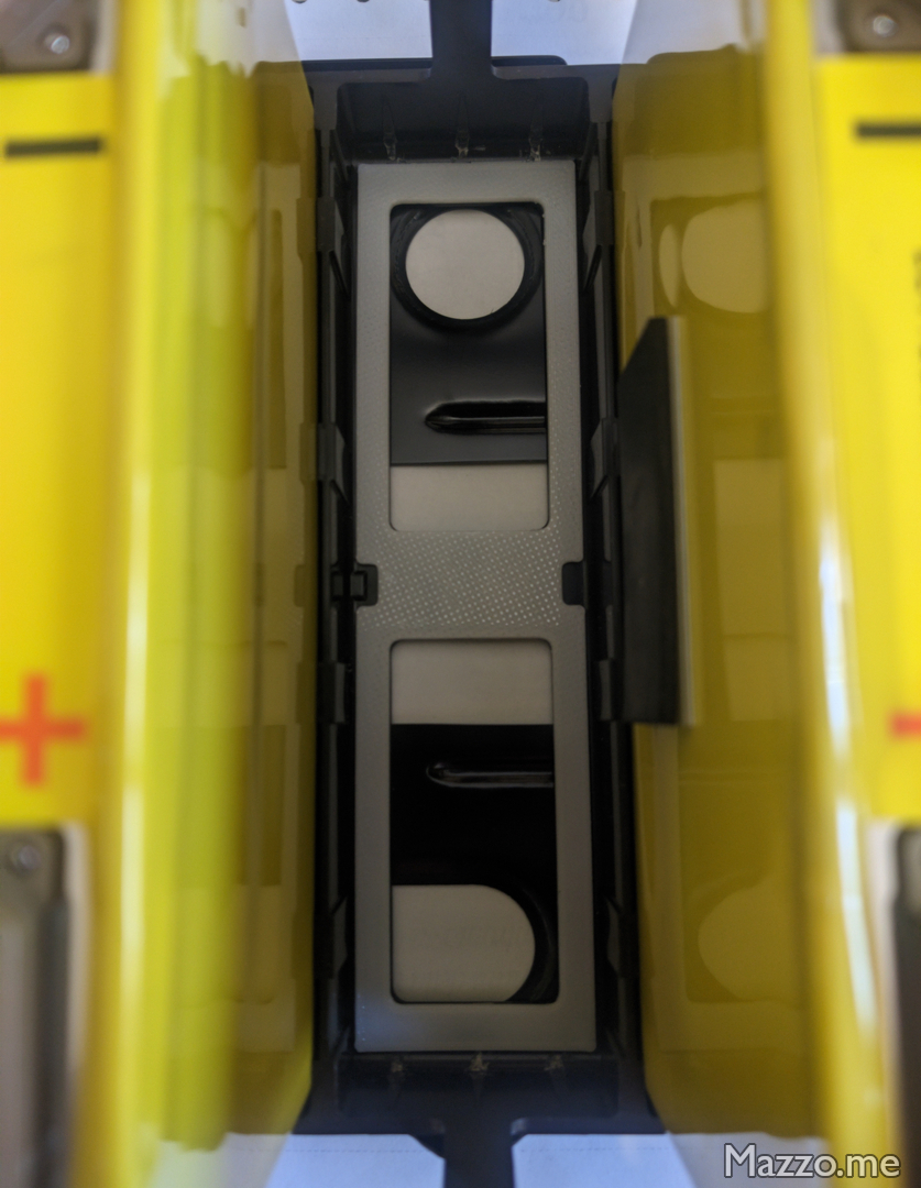
The 3D printed bottom spacer is used to bring the top of the cell case to the same height as the other cells, otherwise the black plastic part that holds the cells in place will not close properly.
In this way, however, the cell terminals are at a different height from the other cells, because they have a different thickness.
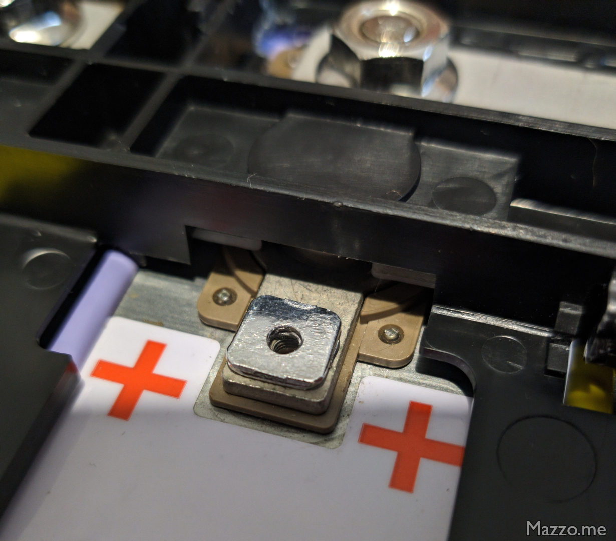
I then built some copper spacers to bring the terminals to the correct height:
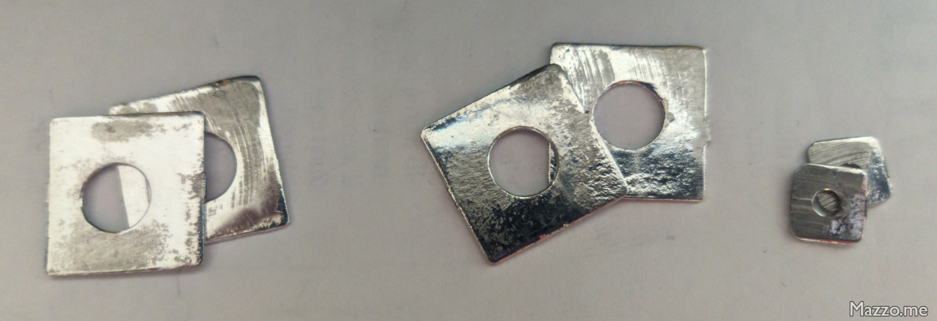
The copper spacers were dip-tinned in a crucible of molten solder and then pressed to achieve as uniform a thickness as possible.
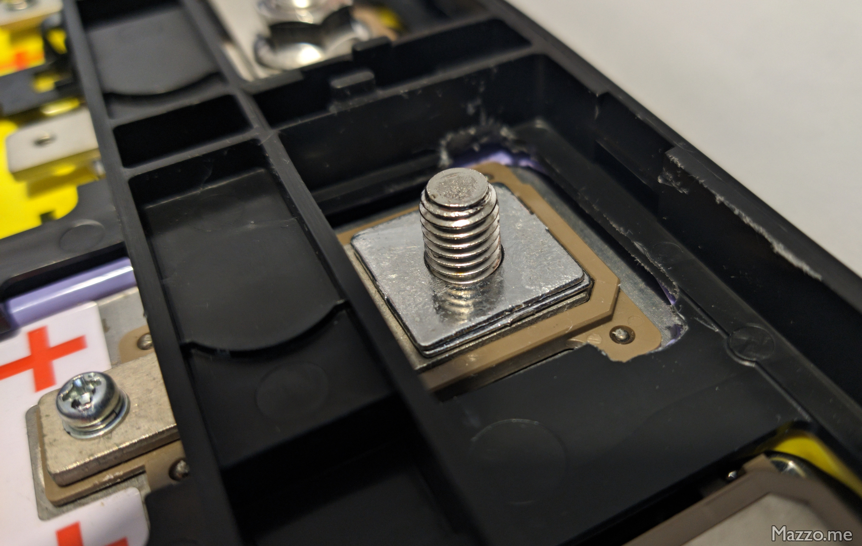
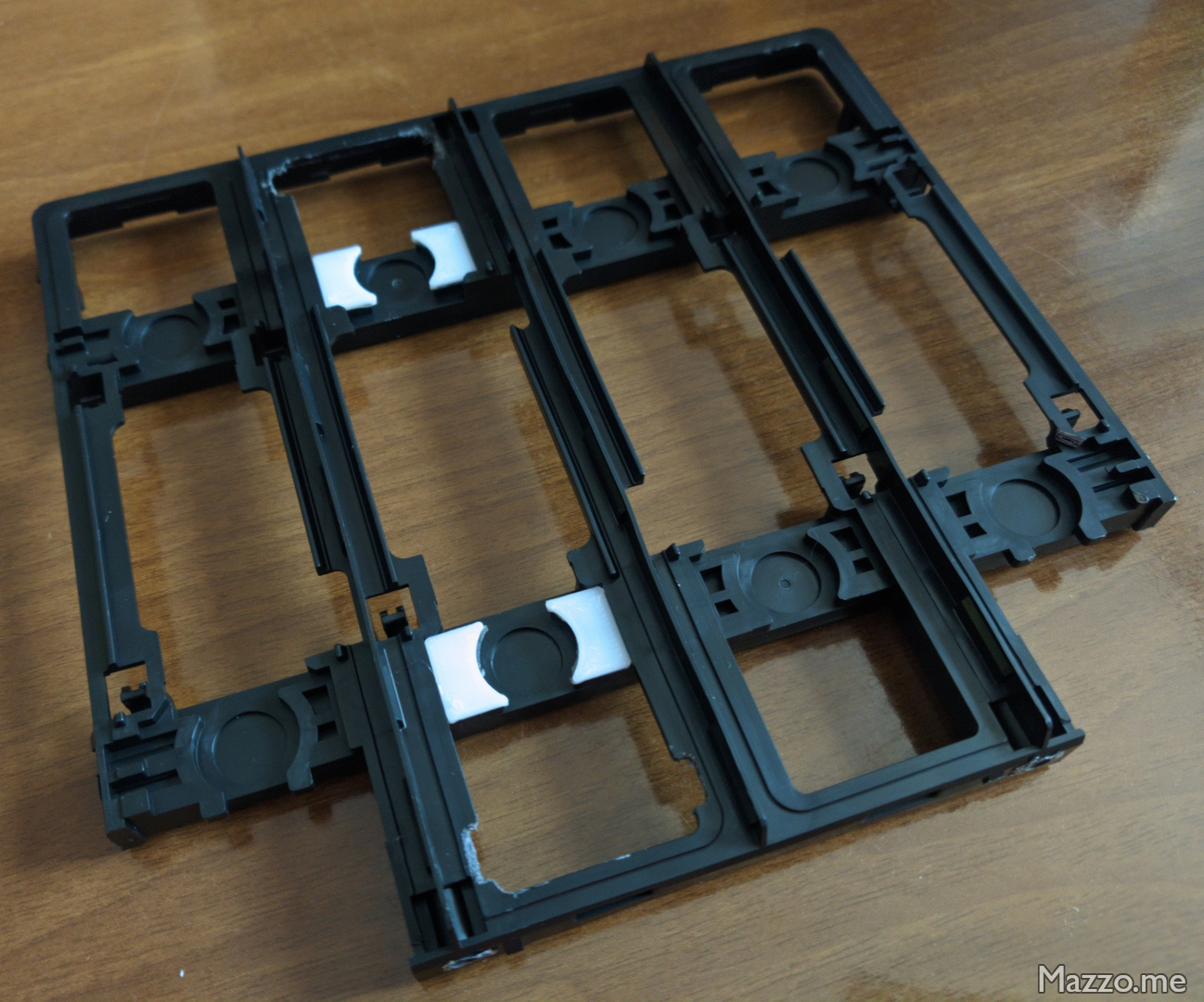
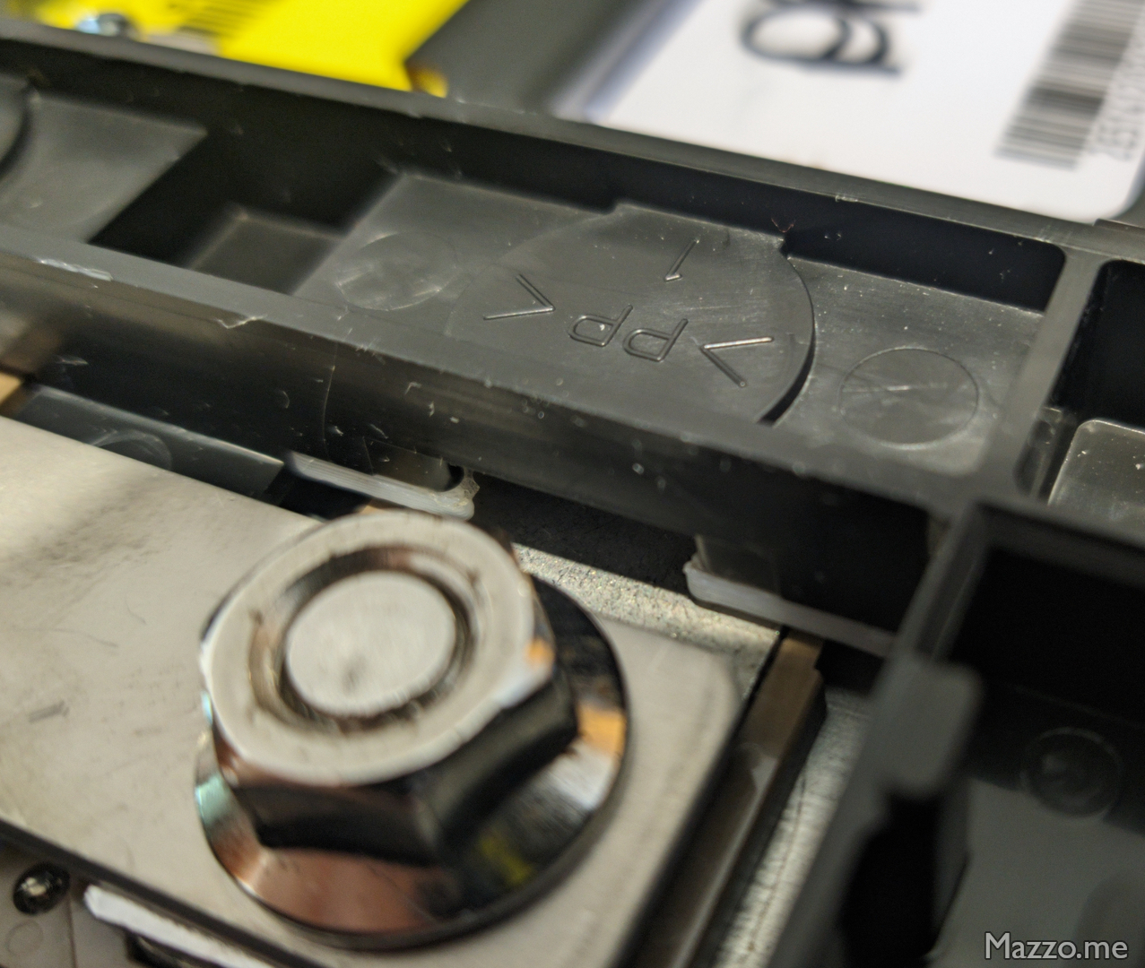
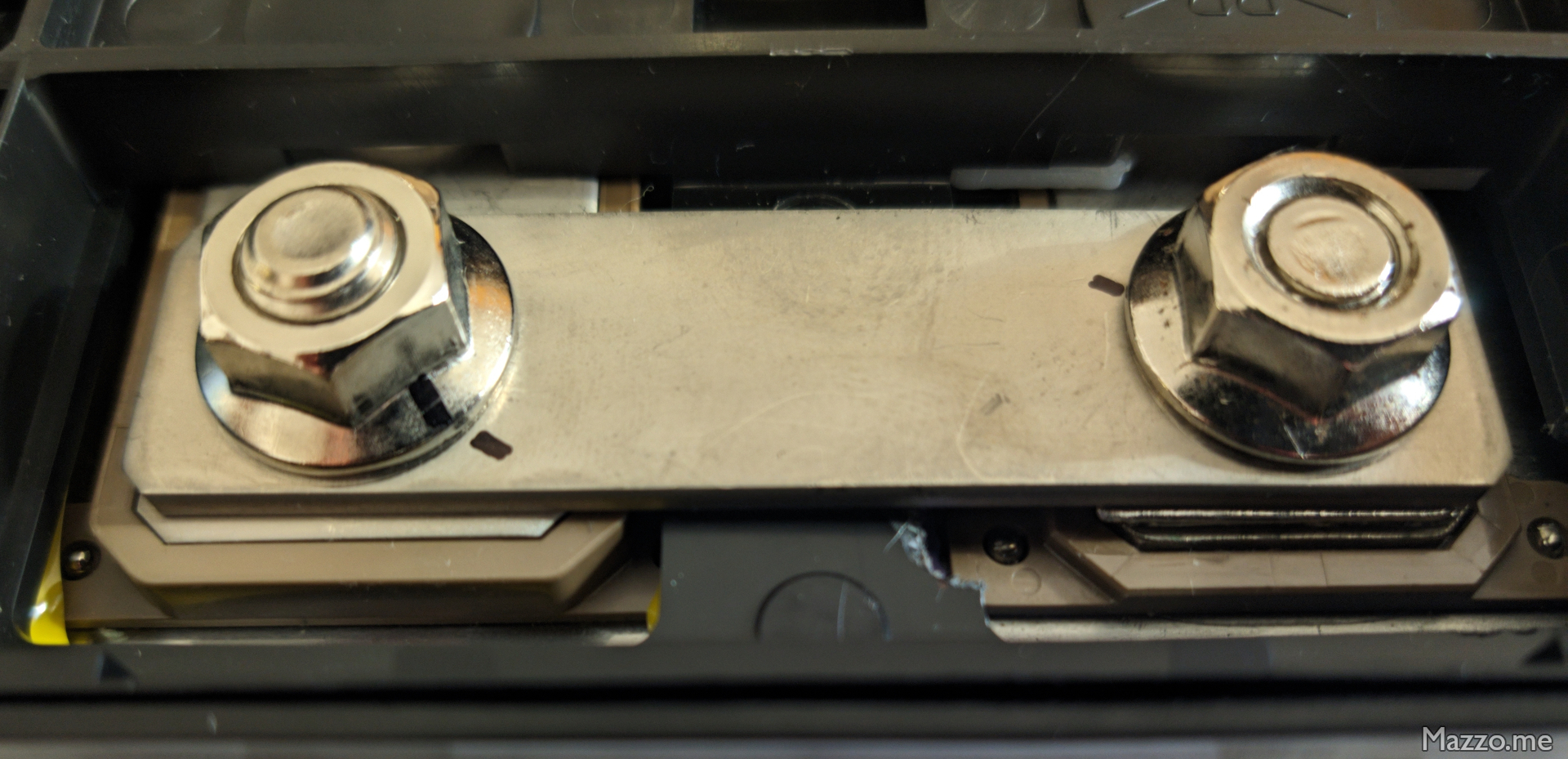
I also had to add spacers to the black plastic part that holds the cells in place to make it rest correctly on the lowest cell:
| LEV50N cell | Value |
|---|---|
| Rated voltage | 3,75 V |
| Operating voltage range | 2,75 - 4,1 V |
| Terminal size | M8 |
| Terminal tightening torque | 13 Nm |
| Charge limit voltage | 4,1 V |
| Charge limit current | < 0,5 A |
| Maximum discharge current | 300 A |
Warning
Before being mounted, the replacement cell must be brought to the same voltage as the other cells to have a balanced battery.
If the residual capacity of the replacement cell is not equal to that of the other cells, it is recommended to fully charge the car battery before starting work.
Battery assembly
- To install the battery, follow the steps in reverse order, taking care when lifting the battery to position and secure it under the car to ensure that the gaskets on the upper battery cover are correctly inserted into the holes in the car chassis.
Lower battery cover
On the lower battery covers you can see the shielding:
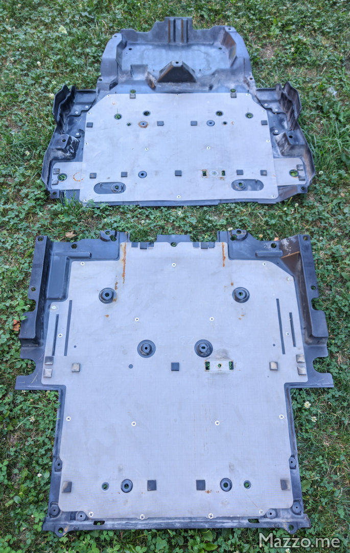
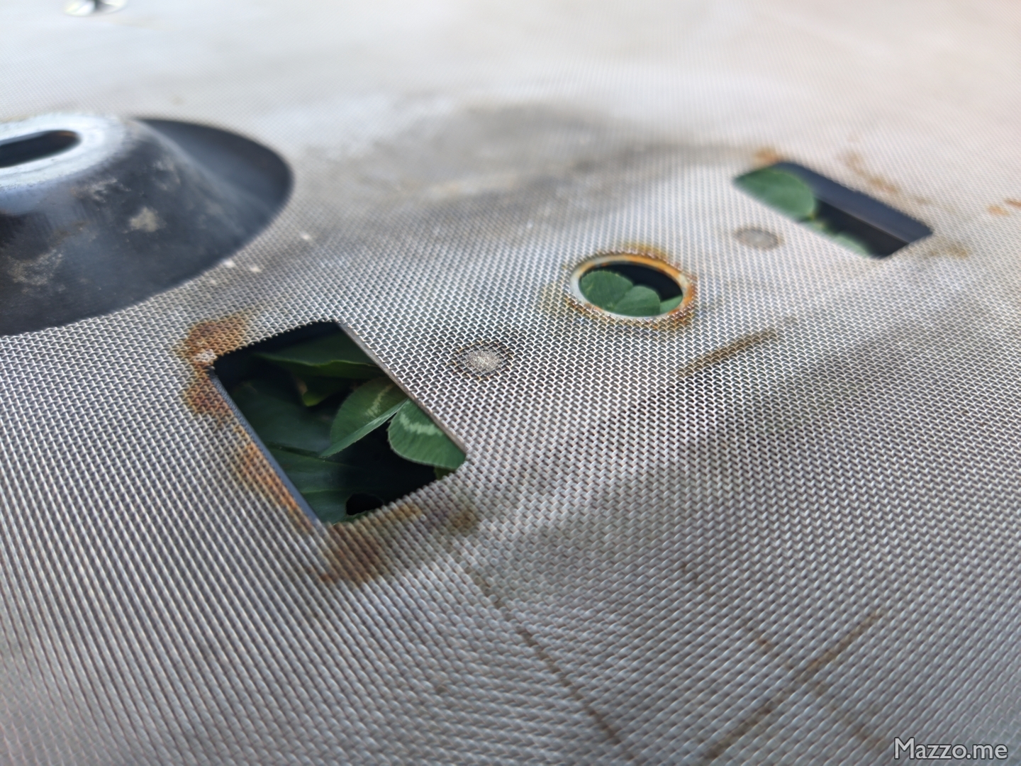
Disconnector access gasket
- From under the driver’s seat, check that the battery disconnector service lid gasket is correctly positioned.
Battery cooling duct gasket
- Once the work is completed and the battery is secured to the car’s frame, it is necessary to work inside the passenger compartment to correctly position the battery cooling duct gasket.
- There is a pre-cut section on the carpet in front of the passenger seat that needs to be cut to access the air duct and gasket:
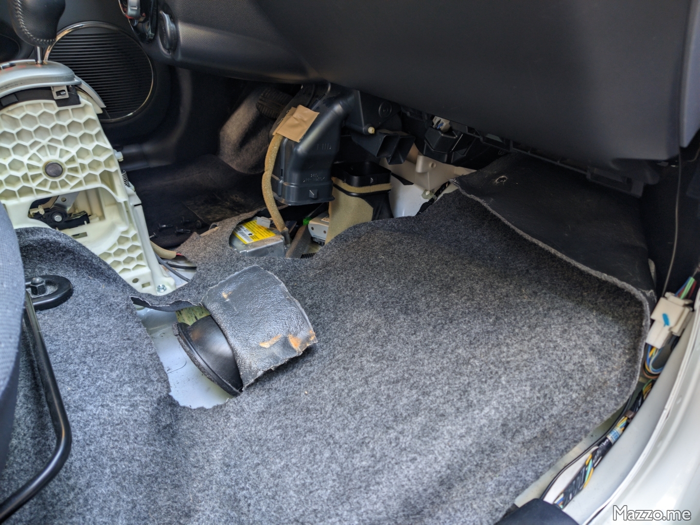
Battery cooling duct disconnected in passenger compartment.
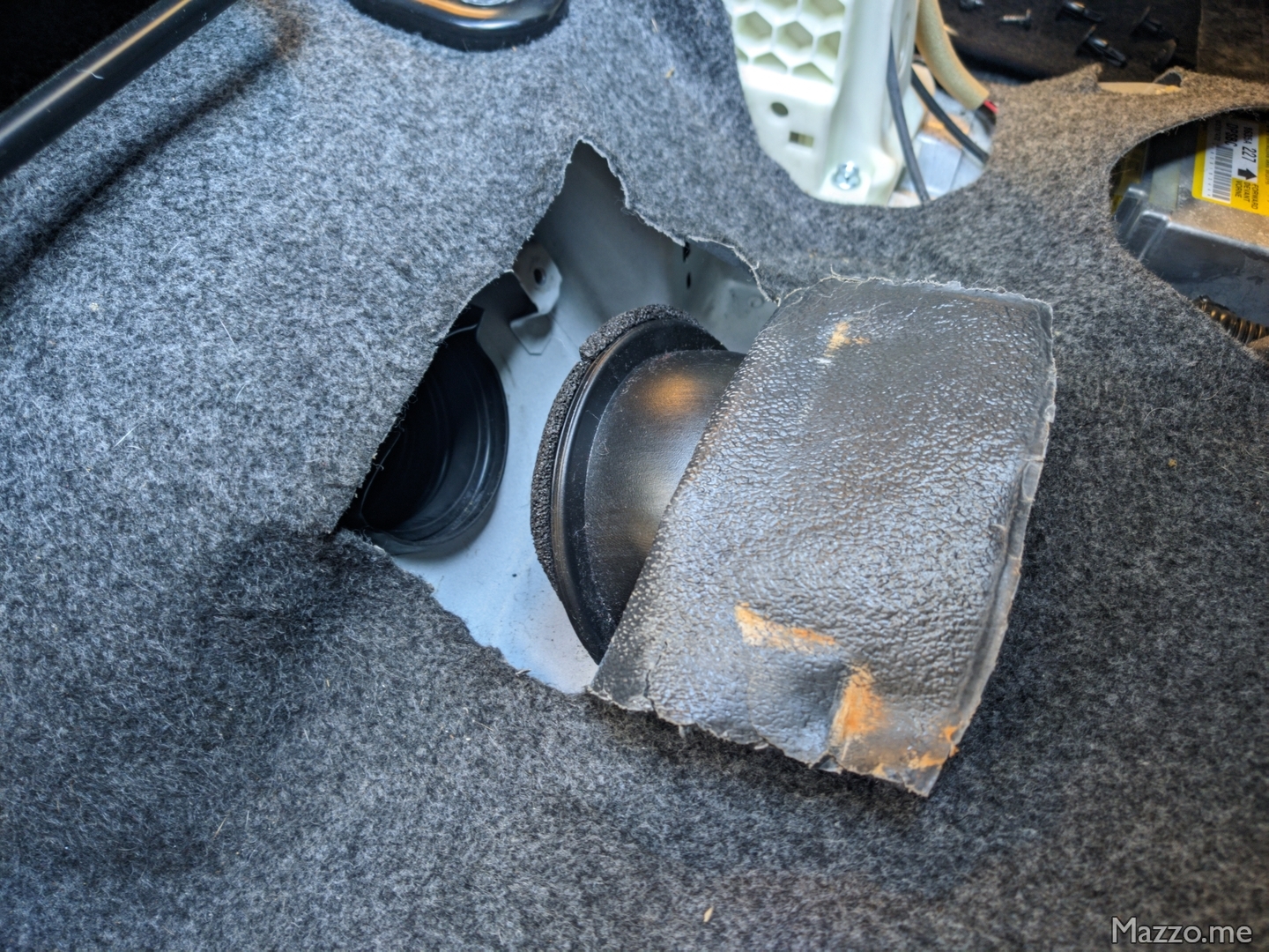
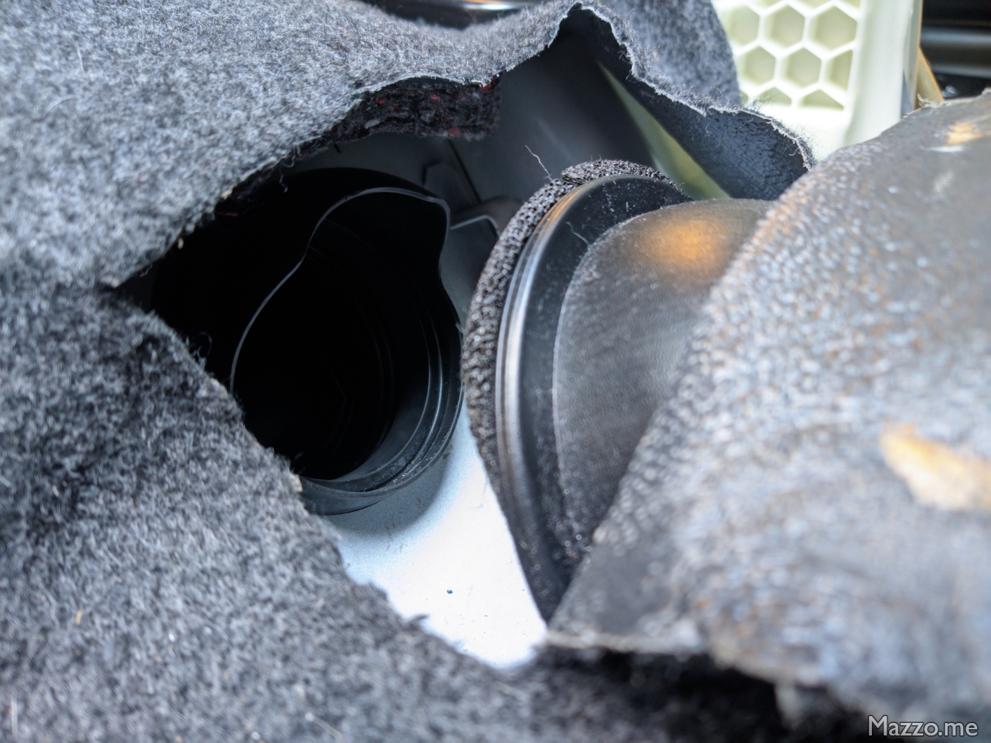
- To gain access to the gasket, you need to disconnect and move forward the duct that carries air to the battery, also removing the central tunnel:
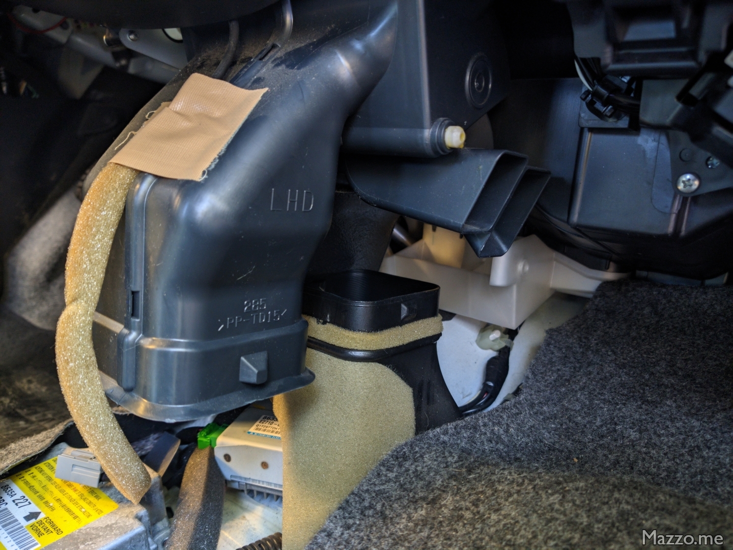
Battery cooling duct moved. - The cut part of the carpet can be closed with Velcro:
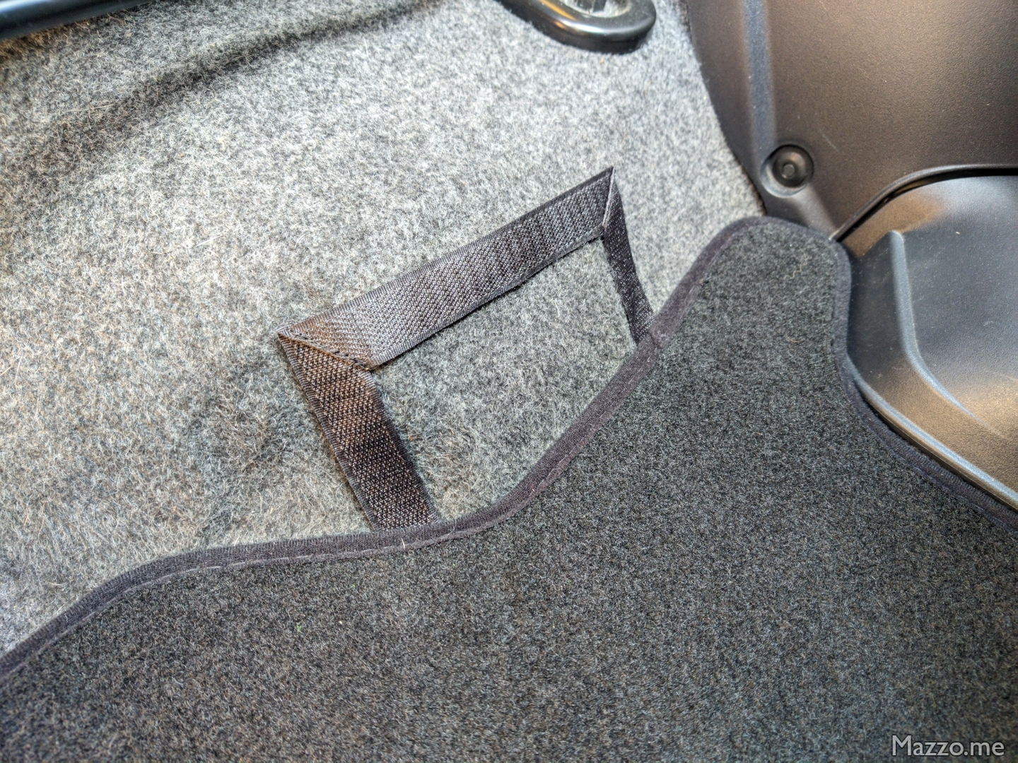
Velcro carpet closure.
Conclusions
After a few weeks of use, the car is running normally and hasn’t had any problems, even when using a different cell than the others, but with similar residual capacity.
Note
Source of technical images: i-MiEV Workshop Manual .